

The Ultimate Engineer’s Guide to PTFE Wear Bands: Virgin vs. Filled
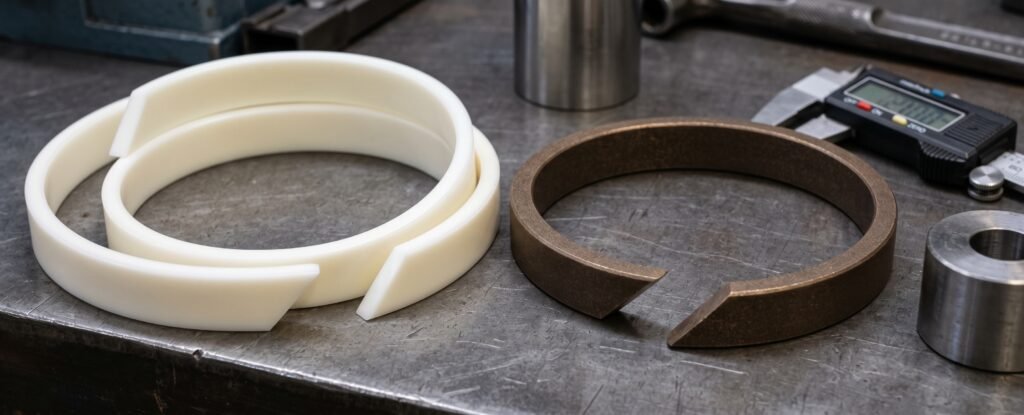
In the precise world of fluid power and non-standard automation equipment design, guide rings—commonly known as wear bands—serve as the critical buffer between moving mechanical components. Their primary function is to absorb radial forces and prevent catastrophic metal-to-metal contact between the piston and the cylinder bore, or the rod and the gland. Selecting the correct guide ring material directly dictates the operational lifespan, precision, and reliability of the entire hydraulic or pneumatic system.
When international procurement teams and design engineers source sealing solutions, the choice almost always narrows down to two foundational materials: Virgin PTFE and Filled PTFE. Understanding the exact performance parameters, mechanical thresholds, and optimal application environments for each is essential for engineering robust industrial equipment.
Virgin PTFE Wear Bands: The Low-Friction Purist
Virgin Polytetrafluoroethylene (PTFE) is an unfilled, unalloyed fluoropolymer. Because of the exceptionally strong carbon-fluorine bonds and high molecular weight, Virgin PTFE offers highly specialized chemical and physical traits that make it indispensable for environments requiring absolute purity and minimal resistance.
Core Performance & Technical Parameters
Virgin PTFE boasts the lowest dynamic and static friction coefficient of any known solid material, typically hovering between 0.02 and 0.06. This virtually eliminates the “stick-slip” phenomenon, ensuring incredibly smooth actuation—a non-negotiable requirement for precision automation mechanisms.
Compressive Strength: 10 MPa to 15 MPa (at room temperature)
Operating Temperature Range: -200°C to +260°C
Maximum Surface Speed: Up to 15 m/s (dry running conditions may reduce this threshold)
Hardness (Shore D): 50 to 60
Water Absorption: < 0.01% (ensuring exceptional dimensional stability)
Ideal Application Scenarios
Because it contains no additives, Virgin PTFE is completely non-toxic and chemically inert (except to molten alkali metals and free fluorine at high temperatures). It is the premier choice for:
Food & Beverage Machinery: Fully compliant with FDA standards for pneumatic cylinders in filling and homogenizing equipment where fluid contamination must be avoided.
Cleanroom & Semiconductor Automation: Emits zero particulate dust or chemical leaching, meeting the strict atmospheric requirements of high-grade cleanrooms.
Precision Pneumatics: Ideal for air cylinders requiring minimal break-away pressure and low-load, high-frequency instrument lifts.
Design Precautions & Limitations
The most significant limitation of Virgin PTFE is its susceptibility to “cold flow” or creep. Under continuous, heavy mechanical loading, the material will gradually deform and flatten out. Therefore, Virgin PTFE must never be specified for heavy-duty hydraulic cylinders or construction machinery facing high radial impacts. When calculating the bearing area, the permissible specific pressure ($P$) should strictly be kept below 2 to 3 N/mm². Additionally, designers must account for its relatively high coefficient of thermal expansion by calculating adequate groove clearances to prevent the band from seizing the cylinder at elevated temperatures.
Filled PTFE Wear Bands: The Heavy-Duty Workhorse
To overcome the low load-bearing capacity and creep inherent to pure PTFE, fluid power engineers developed Filled PTFE wear bands. By compounding the base fluoropolymer with specific ratios of performance additives—such as bronze, carbon, graphite, glass fiber, or molybdenum disulfide (MoS2)—the material is transformed into a highly resilient, heavy-duty industrial guide ring. This is the standard specification for B2B international procurement targeting aggressive industrial applications.
Core Performance & Technical Parameters
The most common variant in global trade is 40% or 60% Bronze-filled PTFE. The bronze matrix radically increases compressive strength, hardness, and thermal conductivity. The enhanced heat dissipation rapidly pulls frictional heat away from the contact surface, preventing thermal degradation during high-frequency cycling.
Compressive Strength: 25 MPa to 40 MPa (a 2x to 3x increase over Virgin PTFE)
Operating Temperature Range: -60°C to +200°C
Maximum Surface Speed: Up to 5 m/s (standard hydraulic conditions)
Hardness (Shore D): 60 to 70
Permissible Specific Pressure ($P$): Up to 15 N/mm² at 25°C, and 8 N/mm² at 80°C
| Feature | Virgin PTFE | Bronze-Filled PTFE (40%) | Carbon-Filled PTFE |
| Friction Coefficient | 0.02 – 0.06 | 0.05 – 0.10 | 0.04 – 0.09 |
| Wear Resistance | Low | Very High | Excellent (Water/Dry) |
| Thermal Conductivity | Poor | Excellent | Good |
| Load Bearing | Light Duty | Heavy Duty | Medium/Heavy Duty |
Ideal Application Scenarios
Filled PTFE is engineered to withstand the punishing environments of modern heavy industry:
Construction & Earthmoving Equipment: Excavator and loader boom cylinders that must endure massive, unpredictable side loads and high operational pressures.
Injection Molding & Forging Presses: Heavy machinery requiring continuous, high-load operation where bronze-filled bands prevent eccentric shaft wear and premature primary seal failure.
Industrial Servo Cylinders: Carbon-filled variants are frequently utilized in high-frequency, dynamic servo systems to mitigate wear from rapid oscillation.
Design Precautions & Limitations
When specifying Filled PTFE, the hardness of the mating metal surface becomes a critical factor. The robust fillers (especially glass fiber and bronze) act as mild abrasives over time. Consequently, the opposing piston rod or cylinder bore should possess a minimum surface hardness of 50 HRC, typically achieved through hard chrome plating or nitriding. Furthermore, while PTFE is chemically inert, the fillers are not. Bronze-filled bands may oxidize or corrode when exposed to certain harsh acids or specific eco-friendly water-based hydraulic fluids; in such cases, carbon or glass-filled PTFE is the superior alternative.
Engineering Standards for Installation & Groove Design
Whether deploying Virgin or Filled PTFE, the mechanical design of the housing groove and the configuration of the wear band’s cut are what ultimately determine system integrity. These are the exacting details scrutinized by European engineering firms and international buyers.
Optimal Cutting Configurations
Wear bands are generally supplied in continuous rolls and cut to specific diameters. The style of the cut affects fluid dynamics and installation:
Straight Cut (90°): The most economical profile, suitable for rotary shafts or low-pressure systems where minor fluid bypass is acceptable.
Angle Cut (30° or 45°): The undisputed industrial standard. The angled profile allows the two ends to slide smoothly past one another during thermal expansion, preventing the band from binding. It also extends the fluid leakage path, providing secondary pressure retention.
Step Cut (Z-Cut): Offers the most complex bypass path, effectively blocking fluid transfer and preventing extrusion. This is reserved for specialized cylinders where the guide ring must also serve a semi-sealing function, though it carries a higher manufacturing cost.
Clearance, Extrusion, and Surface Finish
The radial clearance (the gap between the metal piston and the cylinder bore) must be precisely calculated. The gap must be large enough to prevent metal-to-metal contact under maximum side load, yet tight enough to prevent the primary elastomeric seals (such as polyurethane U-cups or O-rings) from extruding into the gap under extreme pressure. Standard industrial tolerances demand the wear band thickness be held to within ± 0.05 mm.
Finally, surface roughness dictates wear rates. Dynamic moving surfaces (like the cylinder bore) must be polished to an $Ra$ of 0.1 µm to 0.4 µm to establish an optimal lubricating fluid film. Static surfaces (the bottom of the guide groove) should be kept at an $Ra$ of $\le$ 1.6 µm; excessive roughness in the groove will cause the wear band to abrade itself from the back during micro-movements under alternating loads.
What specific mechanical operating pressures or fluid types are you currently working with in your upcoming cylinder design projects?